8 Mapping an ERD to a Relational Database
We use an Entity Relationship Diagram to represent the informational needs of a system. When we are convinced it is satisfactory, we map the Entity Relationship Diagram (ERD) to a relational database and implement it as a physical database. In general, relations are used to hold entity sets and to hold relationship sets. The considerations to be made are listed below. After we present the mapping rules, we illustrate their application in a few examples.
8.1 MAPPING RULES
To complete the mapping from an Entity Relationship Diagram (ERD) to relations, we must consider the entity types, relationship types, and attributes that are specified for the model.
Entity Types
Each entity type is implemented with a separate relation. Entity types are either strong entity types or weak entity types.
Strong, or regular, entity types are mapped to their own relation. The primary key (PK) is chosen from the set of keys available.
Weak entity types are mapped to their own relation, but the primary key of the relation is formed as follows. If there are any identifying relationships, then the PK of the weak entity is the combination of the PKs of entities related through identifying relationships and the discriminator of the weak entity type. Otherwise, the PK of the relation is the PK of the weak entity.
Relationship Types
The implementation of relationships involves foreign keys. Recall, as discussed in point 1) above. If the relationship is identifying, then the primary key of an entity type must be propagated to the relation for a weak entity type. We must consider both the degree and the cardinality of the relationship. In the following examples. examples 1 – 3 deal with binary relationships and example 4 concerns n-ary relationships.
In general, with a one-to-one relationship, a designer has a choice regarding where to implement the relationship. One may choose to place a foreign key in one of the two relations, or in both. Consider placing the foreign key such that nulls are minimized. If there are attributes on the relationship, those can be placed in either relation.
With a one-to-many relationship, the designer must place a foreign key in the relation corresponding to the ‘many’ side of the relationship. Any other attributes defined for the relationship are also included on the ‘many’ side.
A many-to-many relationship must be implemented with a separate relation for the relationship. This new relation will have a composite primary key comprising the primary keys of the participating entity types and any discriminator attribute, plus other attributes of the relationship if any.
n -ary, n>2 A new relation is generated for an n-ary relationship. This new relation has a composite primary key comprising the n primary keys of the participating entity types and any discriminator attribute, plus any other attributes. There is one exception to the formation of the PK: if the cardinality related for any entity type is 1, then the primary key of that entity type is only included as a foreign key and not as part of the primary key of the new relation.
Attributes
- Simple, atomic
These are included in the relation created for the pertinent entity type, many-to-many relationship, or n-ary relationship.
Each multi-valued attribute is implemented using a new relation. This relation will include the primary key of the original entity type. The primary key of the new relation will be the primary key of the original entity type plus the multi-valued attribute. Note that in this new relation, the attribute is no longer multi-valued.
- Composite and Derived attributes are not included.
The above constitutes the standard rules for mapping an ERD to relations. A designer may make other choices but one expects there would be good reasons for doing so.
8.2 Examples
Example 1
Consider the ERD
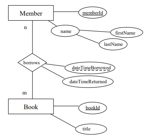
The mapping rules lead to the relations:
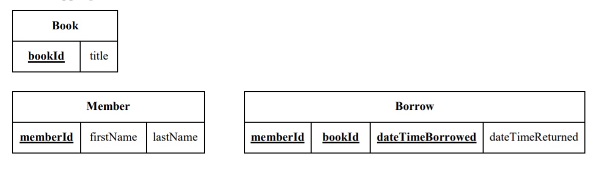
- The Member relation does not have a composite attribute name .
- Since Borrows is a many-to-many relationship the Borrow relation is defined with a composite primary key memberId, bookId, dateTimeBorrowed>.
- memberId in the Borrow relation is a foreign key referencing Member.
- bookId in the Borrow relation is a foreign key referencing Book.
Example 2
Consider the ERD
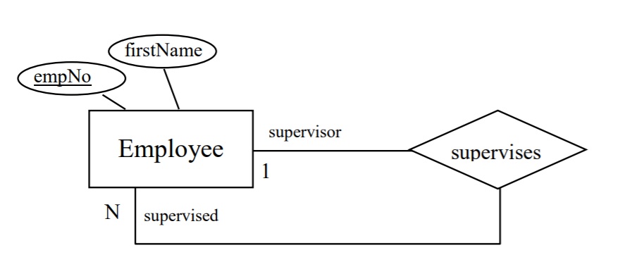
The mapping rules lead to the relation:
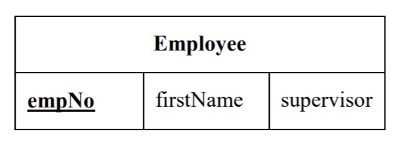
- The attribute supervisor is a foreign key referencing Employee.
- A foreign key is placed on the ‘many’ side of a relationship and so in this case the foreign key references the employee who is the supervisor (the role name on the ‘one’ side); hence the name supervisor was chosen as the attribute name.
Example 3
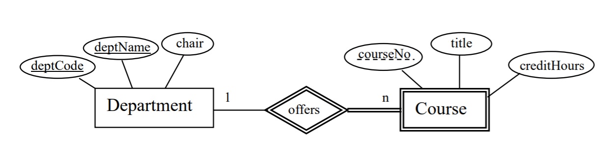
Consider the ERD The mapping rules lead to the relations.
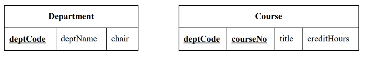
- deptCode was chosen as the primary key of Department.
- deptName is a key and so a unique index can be defined to ensure uniqueness.
- Since Course is a weak entity type and is involved in an identifying relationship, the primary key of Course is composite comprising deptCode, courseNo>.
- deptCode in Course is a foreign key referencing Department.
Exercises
- Map the ERD to relations.
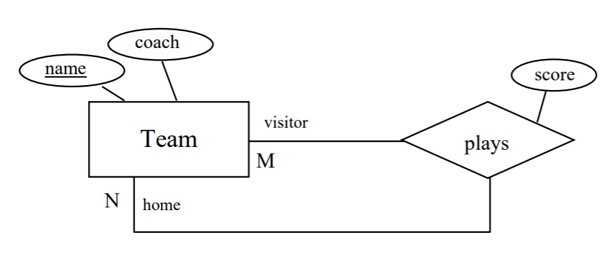
- Map the ERD to relations.
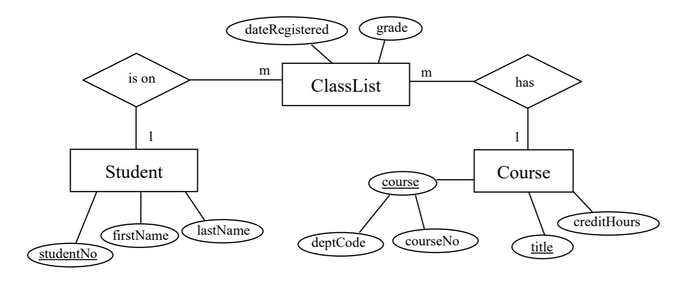
- Map the ERD to relations.
